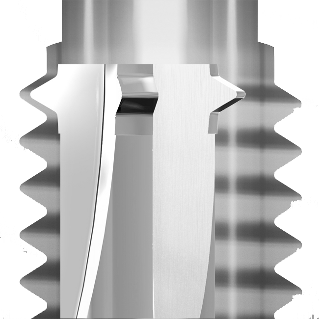
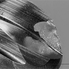
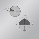
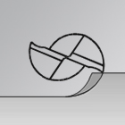
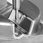
POINTING

What influence does pointing have?
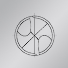
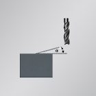
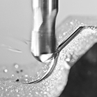
A pointing at the tip of the drill improves the centering of the drill and changes the service life of the cross cutter. The pointing reduces the cross cutter and thus the pressure and friction on the material. As a result of the changed cutting pressure and chip removal, lower feed forces are required during drilling.

SPEED

What is the appropriate
speed?
This depends on the engagement conditions, the machining mode, and the component material. Thereby cutting pressure, chip cross-section, chip formation, and other important factors play a role.

SPEED

At what speed are
Torx®*-contours milled?
We recommend speeds between 15,000 rpm and 40,000 rpm. Depending on the number of teeth of the milling tool and the achievable total feeds.

SPEED

At what speed
are threads milled?
Speed depends on the component material and the thread size and is between 3,000 rpm and 15,000 rpm.

SPEED

At what speed is solid carbide milled?
Depending on the tool diameter and the machining mode, the speed in this case is between 20,000 rpm and 35,000 rpm.

Speed

At what speed is solid carbide machined with the grinding
pin?
Using cooling and flushing, speeds from 22,000 rpm to 50,000 rpm are suitable.

CORNER MILLING

How are corners optimally
milled?
The tool diameter should be at least 0.5 mm smaller than the corner radius of the component, so that the machine performs a constant movement. Select the tool radius 20% to 30% smaller than the component radius.

LEAD-IN RAMP ANGLE

What is the appropriate lead-in ramp angle?
The lead-in ramp angle depends on the tool and material and is usually between 0.2° and 10°.

RUNTIME

Why is the real runtime higher than the simulated one?
If programmed feeds are not reached, the real time is extended compared to the simulation. Constant fz is achieved by a uniform driving motion. In addition, when simulating lead-in/lead-out movements are often not considered.

DIMENSIONAL
DEVIATION

What should be done in case of a dimensional deviation between the target and the actual value of a component?
Many factors can be responsible for this: incorrect data, concentricity, machine errors, tool wear, incorrect strategy and parameters, and much more. With systematic precision, tool wear and thus also dimensional deviations can usually be reduced.

CHATTER MARKS

What should be done to prevent chatter marks in graphite material?
In oder to avoid tool displacement, vibrations, or wear, it is important to control the milling direction, feed, and dust evacuation.

FINISHING
ALLOWANCE

How is the right finishing allowance determined?
This cutting condition is absolutely dependent on material, contour, and component.

CUTTING EDGE
PREPARATION

What is the purpose of cutting edge preparation?
Preparation of the cutting edges increases tool life. Grinding results in minimal irregular edges on the flutes, which are smoothed homogeneously through the preparation. The cutting edges are prepared in optimum design directly during development of the tools.

CUTTING EDGE
PREPARATION

How does preparation of the cutting edge affect process reliability?
Preparation of the cutting edge ensures consistent and reproducible performance due to the improved uniform tool properties.

CUTTING DATA

Which formulas are needed to calculate cutting data?
Cutting speed in m/min = π x diameter x spindle speed 1000 Feed per fl ute in mm = feed rate spindle speed x number of cutter fl utes Material removal in cm³/min = cutting depth x cutting width x feed rate 1000 Cutting width* in mm = √(8 x radius x theoretical roughness depth)

MIRROR SURFACES

How are mirror surfaces
milled?
For a uniformly three-dimensional surface structure, the ap, ae and fz must be adjusted. Individual coordination is required between tool, machine, strategy, material, and parameters.

HELIX

Is a short or long helix
better?
Softer materials require a larger helix angle and thus have a short helix, which allows the chips to flow off better. Hard materials require a large helix angle and thus a long helix.

POINT ANGLE

What do different point angles on drills indicate?
The flatter the angle, the thicker the chip; the sharper the angle, the longer and thinner the chip. Basically, a small point angle is used for a soft material. With increasing hardness of the material, a larger first-cut pressure is required, which a smaller point angle can no longer withstand since this influences the relationship of the chip cross-section.

UNEQUAL DIVISION

What is the purpose of a tool offset division?
Offset division leads to a more stable and quieter tool running: There are always several cutting edges engaged that are not opposite to one another and the risk of vibration is significantly minimized.

TOOL SELECTION

How long does a tool have
to be?
To process a component close to the contour, a tool should have the largest possible diameter and a short free length and programming length.

TOOL SELECTION

How does the component material influence tool
selection?
For an economical and safe chip formation, the cutting tool and the component material must be harmonized.

TOOL SELECTION

How does the machining mode influence tool selection?
Special machining requires tools specially tailored to the process, otherwise only a universal compromise is made. Man, machine, tool, and process must be precisely matched to each other.

TOOL BREAKAGE

What should be done in case of tool breakage?
In addition to checking the parameters and engagement conditions, watch out for overloads, concentricity errors, oscillations and/or vibrations – both in the component and in the tool.

TOOL LOOPING

How do I avoid too much tool looping?
As a rule of thumb, the component radius is selected 1.25 to 1.45 times larger than the tool radius.

TOOTH FEED

What does the tooth feed indicate?
The tooth feed is a guideline for the load on the individual flutes. Production times can be controlled through a varying number of flutes at the same tooth feed. For this reason, this number always depends on the material and tool.

TOOTH FEED

What does tooth feed mean during roughing?
A too large tooth feed during roughing usually leads to tool breakage when the tool is overloaded.

TOOTH FEED

What does tooth feed mean during finishing?
If the tooth feed is too small during finishing, the temperature is insufficiently dissipated over the chip and rubbing occurs at the flute.

TOOTH FEED

What does the tooth feed mean in the case of an inner contour?
The path around the tool circumference (u) is always longer than on the cutter midpoint path. Resulting fz > programmed fz on midpoint path.

TOOTH FEED

What does the tooth feed mean in the case of an outer contour?
The path around the circumference (u) of the tool is always shorter than on the cutter midpoint path. Resulting fz < programmed fz on midpoint path.